Work
Inductive Coil Velocimetry System
Inductive coil system to measure projectile velocity from induced voltage
- Solidworks
- 3D Printing
- Python
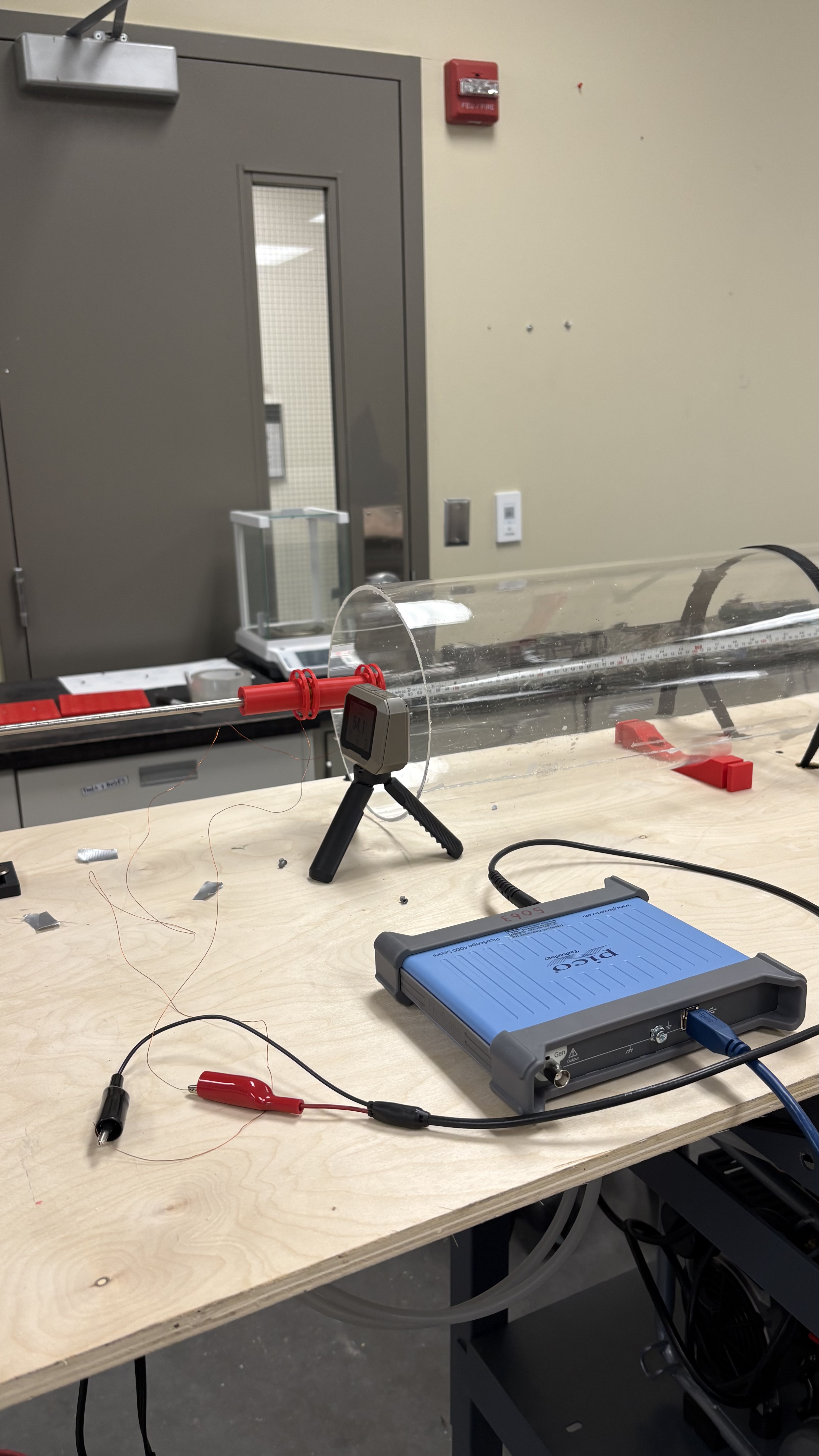
A magnetized projectile passing through a coil of wire will induce a voltage in it. By placing two coils at a known distance apart, and measuring the zero crossings of the bi-polar voltage pulse (when projectile is centered in coil), which acts as a time marker, allows the calculation of the projectiles velocity.
Since the projectile must carry a magnetic field, I attached magnets to the hollow tail of .177 caliber pellets. A sliding twin-spool fixture was designed and 3D-printed to hold the coils at a known distance apart, wound at a certain radius, and be able to slide on to the ‘barrel’ and to cantilever off the ‘barrel’.
Before testing, the expected voltage reading, waveform, maximums and minimums were found using Python from plotting the derived induced EMF formula where EMF = f(…) against the distance.
After testing, and saving the oscilloscope results as CSV, the average velocity between the two coils could be extracted using Python. By finding the four peaks (two bi-polar pulse) and interpolating the index’s of the sign change which represents the ‘zero-crossing’ and it’s corresponding time index, the velocity can be calculated.